5 Steps to Master Drawing Free-body Diagrams

Understanding Free-body Diagrams: The Key to Unlocking Physics and Engineering Secrets
In the realm of physics and engineering, free-body diagrams are an essential tool for visualizing and solving problems. A free-body diagram is a graphical representation of the forces acting on an object, which helps to identify the net force and determine the motion of the object. Mastering the art of drawing free-body diagrams is crucial for students, engineers, and physicists to analyze complex systems and make informed decisions. In this article, we will delve into the world of free-body diagrams and provide a step-by-step guide on how to master drawing them.
Step 1: Identify the Object and its Surroundings
The first step in drawing a free-body diagram is to identify the object of interest and its surroundings. This involves determining the object’s boundaries and the forces that act upon it. Consider the following:
- What is the object’s shape, size, and orientation?
- What are the external forces acting on the object, such as gravity, friction, or applied forces?
- Are there any internal forces, like tension or compression, within the object?
📝 Note: Be sure to clearly define the object's boundaries and identify all external and internal forces acting upon it.
Step 2: Choose a Reference Frame
The next step is to choose a reference frame for your free-body diagram. A reference frame is a coordinate system that helps you describe the motion of the object. There are two common types of reference frames:
- Inertial reference frame: A non-accelerating frame of reference, which is often used for objects at rest or moving at a constant velocity.
- Non-inertial reference frame: An accelerating frame of reference, which is used for objects undergoing acceleration.
Select a reference frame that is convenient for the problem at hand, and make sure to label it clearly on your diagram.
Step 3: Draw the Object and Forces
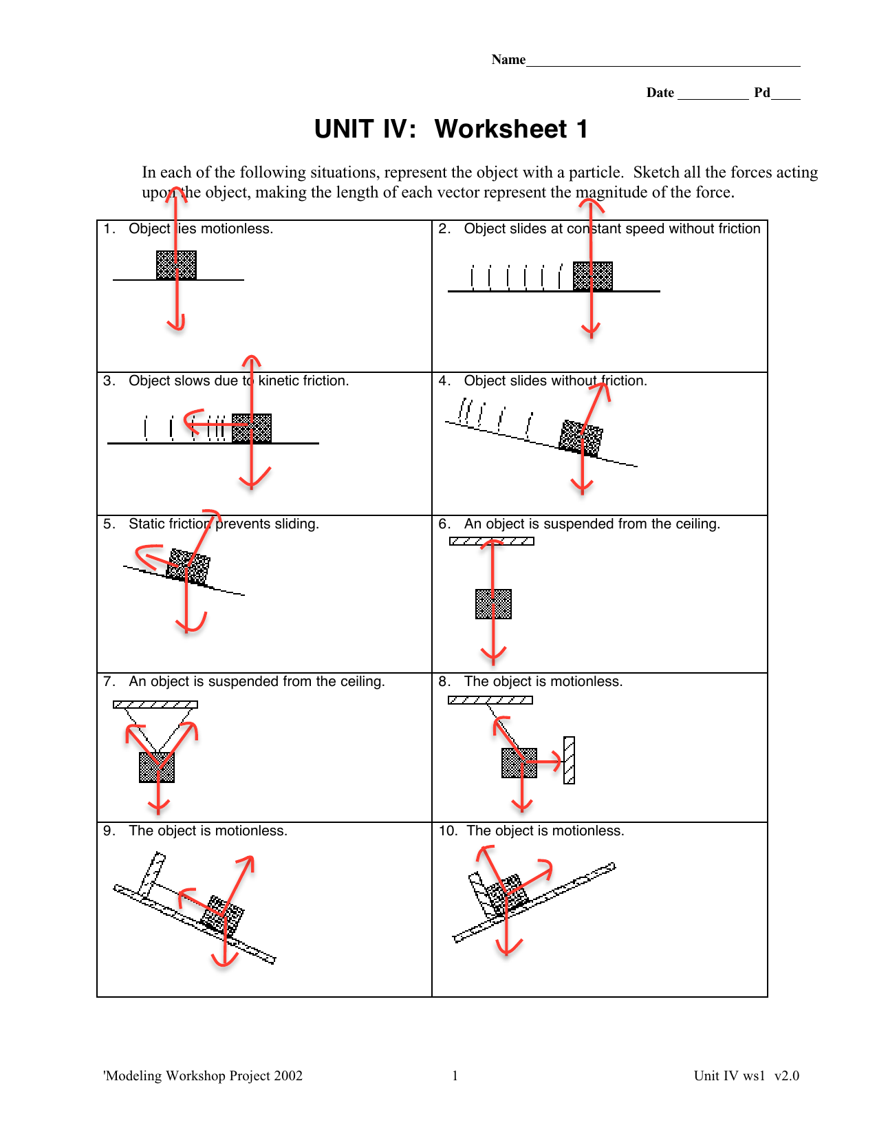
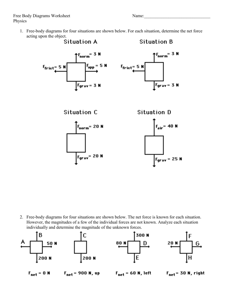
With the object and reference frame defined, it’s time to draw the object and forces. Start by sketching the object in a simplified form, using basic shapes like lines, circles, or rectangles. Then, add the forces acting on the object, using arrows to represent the direction and magnitude of each force.
- Use a consistent scale for your diagram to ensure that the forces are proportional to their magnitudes.
- Label each force clearly, using standard notation and units (e.g., Newtons or pounds).
📝 Note: Be mindful of the force directions and magnitudes, as these will affect the net force and motion of the object.
Step 4: Resolve Forces into Components
In many cases, forces act at angles to the object’s motion or reference frame. To analyze these forces, you need to resolve them into components. This involves breaking down each force into its x- and y-components, using trigonometry or geometry.
- Use the cosine and sine functions to find the components of each force.
- Label each component clearly, using subscripts to denote the direction (e.g., Fx, Fy).
Step 5: Calculate the Net Force and Determine Motion
The final step is to calculate the net force acting on the object and determine its motion. To do this, you need to:
- Add the x- and y-components of each force to find the net force in each direction.
- Determine the magnitude and direction of the net force, using the Pythagorean theorem or trigonometry.
- Use the net force to determine the motion of the object, applying Newton’s laws of motion as needed.
📝 Note: Be sure to check your units and calculations carefully, as small errors can lead to significant mistakes in your analysis.

| Force | x-Component | y-Component |
|---|---|---|
| F1 | F1x = F1 cos(θ) | F1y = F1 sin(θ) |
| F2 | F2x = F2 cos(φ) | F2y = F2 sin(φ) |
| Net Force | Fnet,x = F1x + F2x | Fnet,y = F1y + F2y |
With these 5 steps, you’ll be well on your way to mastering the art of drawing free-body diagrams. Remember to practice regularly and apply these skills to a wide range of problems to become proficient in your analysis.
In conclusion, drawing free-body diagrams is an essential skill for anyone working in physics and engineering. By following these 5 steps, you’ll be able to create accurate and informative diagrams that help you analyze complex systems and make informed decisions.
What is the purpose of a free-body diagram?
+A free-body diagram is a graphical representation of the forces acting on an object, used to identify the net force and determine the motion of the object.
How do I choose a reference frame for my free-body diagram?
+Choose a reference frame that is convenient for the problem at hand, and make sure to label it clearly on your diagram. There are two common types of reference frames: inertial and non-inertial.
What are the 5 steps to drawing a free-body diagram?
+The 5 steps are: (1) identify the object and its surroundings, (2) choose a reference frame, (3) draw the object and forces, (4) resolve forces into components, and (5) calculate the net force and determine motion.
Related Terms:
- Free body diagram Worksheet PDF
- Free body diagram maker


